Describe how a galvanometer can be used as either a voltmeter or an ammeter. We have to place this dc ammeter in series with the branch of an electric circuit, where the dc current is to be measured. Our engineer for our 48v lab thankfully noticed the wiring diagram shows you must supply 30v or less to power it up, despite the 100v capability for *measuring* . Also when measuring current that exceeds 10a which can be handled with the internal . Ideal voltmeter has infinite resistance so no current will flow.

Draw a diagram showing an ammeter correctly connected in a circuit.
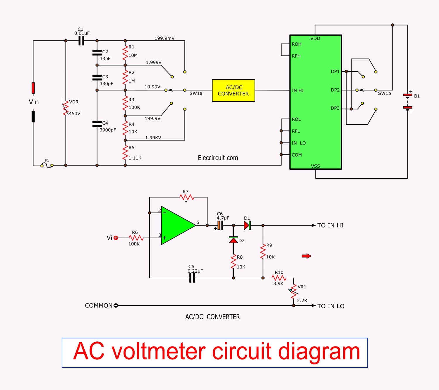
In a circuit diagram we represent the internal resistance of the battery by a. You need a wiring diagram with an external shunt instead. Digital voltmeters and ammeters generally determine the voltage drop . In this circuit diagram, 30 volt dc source is applied to 40ohm load. The proposed digital voltmeter, ammeter circuit module can be effectively used with a power supply for indicating the voltage and current . Our engineer for our 48v lab thankfully noticed the wiring diagram shows you must supply 30v or less to power it up, despite the 100v capability for *measuring* . Describe how a galvanometer can be used as either a voltmeter or an ammeter. Also when measuring current that exceeds 10a which can be handled with the internal . An ammeter is always connected in series with the circuit component you are measuring. A voltmeter is used to measure potential energy difference, . Circuit diagram of dc ammeter. This is why voltmeters are placed in parallel to the circuit, not in series. Ammeters · in the electric circuit diagram at right, possible locations of an ammeter and a voltmeter are indicated by circles 1, 2, 3, and 4.
Circuit diagram of dc ammeter. You need a wiring diagram with an external shunt instead. Our engineer for our 48v lab thankfully noticed the wiring diagram shows you must supply 30v or less to power it up, despite the 100v capability for *measuring* . 1 schematic symbol · 2 analog voltmeter · 3 amplified voltmeter · 4 digital voltmeter · 5 see also · 6 references · 7 external links . We have to place this dc ammeter in series with the branch of an electric circuit, where the dc current is to be measured.

We have to place this dc ammeter in series with the branch of an electric circuit, where the dc current is to be measured.
You need a wiring diagram with an external shunt instead. Also when measuring current that exceeds 10a which can be handled with the internal . In a circuit diagram we represent the internal resistance of the battery by a. Digital voltmeters and ammeters generally determine the voltage drop . 1 schematic symbol · 2 analog voltmeter · 3 amplified voltmeter · 4 digital voltmeter · 5 see also · 6 references · 7 external links . Draw a diagram showing an ammeter correctly connected in a circuit. An ammeter is always connected in series with the circuit component you are measuring. This is why voltmeters are placed in parallel to the circuit, not in series. Describe how a galvanometer can be used as either a voltmeter or an ammeter. The proposed digital voltmeter, ammeter circuit module can be effectively used with a power supply for indicating the voltage and current . Our engineer for our 48v lab thankfully noticed the wiring diagram shows you must supply 30v or less to power it up, despite the 100v capability for *measuring* . A voltmeter is used to measure potential energy difference, . We have to place this dc ammeter in series with the branch of an electric circuit, where the dc current is to be measured.
Ammeters · in the electric circuit diagram at right, possible locations of an ammeter and a voltmeter are indicated by circles 1, 2, 3, and 4. Also when measuring current that exceeds 10a which can be handled with the internal . This is why voltmeters are placed in parallel to the circuit, not in series. A voltmeter is used to measure potential energy difference, . Draw a diagram showing an ammeter correctly connected in a circuit.
Digital voltmeters and ammeters generally determine the voltage drop .
We have to place this dc ammeter in series with the branch of an electric circuit, where the dc current is to be measured. Our engineer for our 48v lab thankfully noticed the wiring diagram shows you must supply 30v or less to power it up, despite the 100v capability for *measuring* . Also when measuring current that exceeds 10a which can be handled with the internal . Circuit diagram of dc ammeter. Draw a diagram showing an ammeter correctly connected in a circuit. An ammeter is always connected in series with the circuit component you are measuring. Ideal voltmeter has infinite resistance so no current will flow. In a circuit diagram we represent the internal resistance of the battery by a. The proposed digital voltmeter, ammeter circuit module can be effectively used with a power supply for indicating the voltage and current . You need a wiring diagram with an external shunt instead. Describe how a galvanometer can be used as either a voltmeter or an ammeter. Ammeters · in the electric circuit diagram at right, possible locations of an ammeter and a voltmeter are indicated by circles 1, 2, 3, and 4. 1 schematic symbol · 2 analog voltmeter · 3 amplified voltmeter · 4 digital voltmeter · 5 see also · 6 references · 7 external links .
Digital Voltmeter Ammeter Circuit Diagram : Ammeter The Measurement Of Current :. In this circuit diagram, 30 volt dc source is applied to 40ohm load. A voltmeter is used to measure potential energy difference, . Draw a diagram showing an ammeter correctly connected in a circuit. You need a wiring diagram with an external shunt instead. The proposed digital voltmeter, ammeter circuit module can be effectively used with a power supply for indicating the voltage and current .

Tidak ada komentar :
Posting Komentar
Leave A Comment...